Guidelines for multi-point suspended scaffolds
Read this guideline to learn about the roles and responsibilities of professional engineers, constructors, employers, supervisors and workers when designing, constructing and using multi-point suspended scaffolds.
1. Introduction
These guidelines are being updated to reflect amendments to O. Reg. 213/91 (Construction Projects) that came into force on January 1, 2017.
The Regulations for Construction Projects [Ontario Regulation 213/91] were amended by Ontario Regulation 85/04, which added specific requirements for the design, construction and use of multi-point suspended scaffolds (MPSS) in subsections 142.1 to 142.8, along with the definitions for "multi-point suspended scaffold", "safety factor", and "traverse" in subsection 1(1) These amendments came into effect October 1, 2004. Sections 137 to 142 of Ontario Regulation 213/91 are no longer applicable to MPSS.
This guideline is intended to provide assistance to professional engineers, constructors, employers, supervisors and workers with an overview of the design, construction and use of multi-point suspended scaffolds.
The information contained in this guideline is not intended to be all-inclusive nor should it be interpreted as replacing or modifying the requirements of the Occupational Health and Safety Act and the Regulations for Construction Projects (the Regulation). These legal requirements should be referred to when using this guideline.
This resource does not replace the Occupational Health and Safety Act (OHSA) and its regulations and should not be used as or considered legal advice. Health and safety inspectors apply and enforce these laws based on the facts they find in the workplace.
2. Purpose of the guideline
The purpose of this guideline is to clarify the requirements for multi-point suspended scaffolds (MPSSs) in sections 142.1 to 142.8 of the Regulations for Construction Projects.
The guideline highlights the major components of an MPSS, design methods, design loads, load factors and safety factors to be considered in the design, system redundancy, design drawings and what they should include. To assist in understanding the requirements made under the Occupational Health and Safety Act, this guideline explains the sections of the regulations for MPSS that deal with the responsibilities of the professional engineer and responsibilities of the constructor, employer, supervisor and worker.
In designing an MPSS, a professional engineer must ensure that the minimum design criteria set out in the Regulations are met when following other applicable codes and standards.
3. Definitions
3.1 Terms defined in subsecction 1(1) of the act and subsection 1(1) of the Regulation
The following definitions have been extracted from section 1(1) of the Occupational Health and Safety Act, 1990 and Section 1(1) of the Regulations for Construction Projects and are provided below for reference in this guideline:
"Multi-point suspended scaffold" (MPSS), means a suspended scaffold or suspended work platform or a system of suspended scaffolds or suspended work platforms, each scaffold or platform being more than 750 millimetres in width, that is supported from an overhead support system by at least three primary load- carrying means of suspension to maintain the system's stability.
"Building Code", means Ontario Regulation 350⁄06 made under the Building Code Act, 1992.
"Competent person", means a person who:
- is qualified because of knowledge, training and experience to organize the work and its performance
- is familiar with this act and the regulations that apply to the work
- has knowledge of any potential or actual danger to health or safety in the workplace
"Competent worker", in relation to specific work, means a worker who,
- is qualified because of knowledge, training and experience to perform the work
- is familiar with the Occupational Health and Safety Act and with the provisions of the regulations that apply to the work
- has knowledge of all potential or actual danger to health or safety in the work
"Constructor", means a person who undertakes a project for an owner and includes an owner who undertakes all or part of a project by himself or by more than one employer.
"Employer", means a person who employs one or more workers or contracts for the services of one or more workers and includes a contractor or subcontractor who performs work or supplies services and a contractor or subcontractor who undertakes with an owner, constructor, contractor or subcontractor to perform work or supply services.
"Professional engineer", means a person who is a professional engineer within the meaning of the Professional Engineers Act.
"Safety factor", means the ratio of the failure load to the specified load or rated load.
"Traverse", when used in relation to a multi-point suspended scaffold, means to move the scaffold horizontally, in a controlled manner along the building or structure to which it is attached.
"Worker", means a person who performs work or supplies services for monetary compensation but does not include an inmate of a correctional institution or like institution or facility who participates inside the institution or facility in a work project or rehabilitation program.
4. Multi-point suspended scaffolds (MPSS) overview
4.1 Use of MPSS
Multi-point suspended scaffolds are suspended from a permanent building or structure and are used as a work platform for a variety of tasks on construction projects and industrial workplaces. Multi-point suspended scaffolds vary in size and capacity depending on their application.They range from large area MPSS commonly used for bridge repair and restoration work to small scaffolds used for access and inspection applications. MPSS are also used for masonry work particularly in high-rise building construction.
Multi-point suspended scaffold may be designed and constructed to move or traverse horizontally, or move vertically along the structure from which they are suspended, or to remain stationary.
4.2 Description of major components of an MPSS
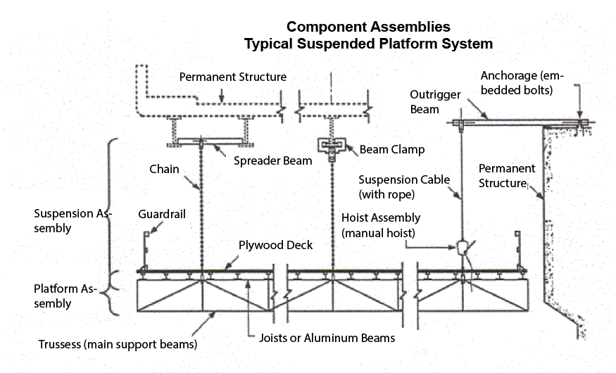
A Multi-Point Suspended Scaffold (MPSS)generally consists of the following major components: (refer to sketch 1 in Appendix A):
- Platform assembly: the platform surface and structure, which may be one level or multiple levels.
- Suspension system: the suspension system includes wire ropes, chains and cables, and the anchorage system. It also includes a hoisting mechanism: an assembly that will allow the platform to be moved by mechanical means.
4.2.1 Platform assembly
The platform consists of three main components:
- The main supporting beams or trusses
- The joists
- The deck surface
The platform may be constructed of wood, steel or aluminium.
4.2.2 Suspension system
The suspension system contains the following:
- Suspension assembly includes wire ropes, chains or cables and rigging hardware to connect the platform to the overhead structure, which is normally a permanent structure;
- Hoisting mechanism, where the scaffold is to be raised or lowered; and
- Anchorage system, which includes outrigger beams, beam clamps, cross tubes, trolley mechanism and other related hardware.
4.2.2.1 Suspension assembly
The suspension assemblies are the primary support system for Multi-Point Suspended Scaffolds. The suspension system assembly connects the platform structure to the overhead structure. The suspension assembly consists of wire ropes, chains or cables.
Wire ropes and chains
The most common type of suspension system assembly is steel wire rope or chains to support or suspend the platform from a permanent or temporary structure. Threaded steel rods and steel tubes are also commonly used. This type of assembly normally includes the wire rope or chain, the appropriate rigging hardware, the stirrups or clamps used to attach the wire rope or chain to the main support beams of the platform, and the beam clamps or outrigger beams. The beam clamps and outrigger beams are part of the anchorage system and are attached directly to the permanent structure.
4.2.2.2 Hoisting mechanism
A hoisting mechanism is connected to the suspension system when the MPSS is designed to move vertically. The two main categories of hoists are manually operated and power operated hoists.
Manually operated hoists
The most common hoists are traction type, which are used with a wire ropes suspension system.
Power operated hoists
Power Hoists are operated by electric, hydraulic, or pneumatic power. Most of these units use a motor driven sheave or drum assembly.
4.2.2.3 Anchorage system
The anchorage system for the MPSS includes the following:
Trolley and rollers
Trolley and rollers are used when the platform is designed to traverse or move horizontally. When the trolley mechanisms are attached to the permanent structure, they are considered part of the anchorage system. Trolley mechanisms are sometimes used at the platform level and as such are considered part of the suspension assembly. The use of movement-limiting devices would ensure that trolley movement is controlled.
Outrigger beams
Outrigger beams may be used as anchorage for an MPSS and are part of the suspension system. They are generally supported on the permanent structure and over hang the edge to provide an attachment for the wire rope or chains of the suspension assembly.
5. Design requirements
Section 142.2(1) requires that a professional engineer design the MPSS. The professional engineer must be licensed in Ontario and must have the necessary knowledge and experience to design MPSSs and their components.
Note: Subsection 142.2(14) requires that the constructor have the professional engineer, responsible for the structural integrity of the permanent building or structure from which the scaffold is suspended, provide a written report on the suitability of the supporting structure to support the design loads imposed by the MPSS.
In order to do this, the MPSS design engineer must provide the loading information to the engineer responsible for the permanent building or structure. The information should contain but is not limited to the following:
- The loading imparted by the MPSS, including wind loads on the MPSS, localized loading caused by a failure in a suspension point, etc.
- The fall arrest forces for workers on the platform
- In the case of bridges, traffic movement, possibility of lane closures that may cause imbalanced loading
- Any other loading that in the opinion of the professional engineer may affect the supporting structure
5.1 Loading considerations:
Section 142.2 (2) indicates both the live loads and dead loads that must be used in the design of the MPSS.
5.1.1 Dead loads:
Dead loads are the weight of the MPSS and its components including the loads imposed by the guardrail system. Fixed scaffold and ancillary structures that are constructed as part of the MPSS may be considered as part of the dead load.
5.1.2 Live loads:
The live loads to be taken into consideration when designing an MPSS are, but are not limited to:
- construction material
- equipment
- debris from demolition, including grit from abrasive (sand) blasting
- workers
- loads from traversing or otherwise moving the MPSS
The minimum uniformly distributed live loading that the MPSS is to be designed to is dependent on its intended use.
The MPSS must be designed for a minimum live load of 1.2 kN/m2 uniformly distributed over the platform surface, except:
- if the MPSS is intended for masonry work, it shall be designed for a live load of at least 2.4 kN/m2 excluding storage of masonry units;
- if the MPSS is used for heavy-duty work such as demolition or storage of masonry units or other related material or equipment, it shall be designed for a live load of at least 3.6 kN/m2 uniformly distributed over the platform surface.
5.1.2.1 Additional live load considerations
Subsection 142.2(3) requires in addition to the loads specified in subsection (2), a multi-point suspended scaffold shall be able to support or resist the following concentrated loads and wind loads.
5.1.2.1.1 Concentrated loads
Subsection 142.2(3) requires that in addition to the uniformly distributed live and dead loads, the MPSS must be able to support or resist a concentrated load of 1.1 kN on an area measuring 0.3 metres by 0.3 metres located on the platform at a position having the most adverse effect on the component under consideration. This concentrated load will be factored with a live load factor of 3.0 for MPSS and structural members and 4.0 for suspension systems.
5.1.2.1.2 Loads due to abrasive (sand) blasting operations
If the MPSS is to be used for abrasive blasting operations, then an additional live load allowance for 25 mm grit accumulation across the entire platform area must be included. It is recommended that the unit weight of the grit be specified and verified during field inspection.
5.1.3 Wind loads
Subsection 142.2(3)(b) indicates that the MPSS shall be designed for wind loads determined in accordance with Table 2.5.1.1 (Design Data for Selected Locations in Ontario) as per section 4.1.8 of the Building Code Act, 1992, assuming a probability factor of at least one in ten.
The effect of wind loading on any environmental enclosures on the MPSS must be taken into account.
5.1.3.1 Special consideration for the wind loading
The wind load derived from Table 2.5.1.1 of the Building Code Act, 1992, may be reduced by up to 30% if the professional engineer who designs the MPSS determines it appropriate to do so. If the professional engineer does reduce the wind load, he/she must make such a determination in writing.
5.1.4 Any other applied loads
Subsection 142.2(3)(c) indicates that in addition to the above loads, the MPSS shall be designed for any other loads likely to be applied to it.
Examples include:
- Stock piling or storage of material
- Dynamic effects of moving equipment
- Material receiving areas
5.2 Methods for designing the MPSS
The regulation offers alternative design methods which may be used for the design of the MPSS:
- Limit States Design
- Working Stress Design
- Ultimate Strength Design (testing to failure for components)
5.2.1 Limit States Design
Subsections 142.2(2),(3),(4),(5),(6),(7) and (8) of the Regulation set out the design and load criteria of an MPSS, based on the Limit States Design method in section 4.1.3 of the Building Code Act, 1992.
The values of the load factors stated in subsections 142.2(7) and (8) of the Regulation replace the values of the load factors described in section 4.1.3 of the Building Code and must be used instead. The live load factors for the MPSS are different from those of the Building Code as the MPSS is a temporary structure while the Building Code addresses permanent structures. The MPSS must be designed to have sufficient strength and stability so that the factored resistance is greater than or equal to the factored loads as presented in section 4.1.3.2 of the Building Code. The equation below (see section 4.1.3.2 of the Building Code) was modified for the design of the MPSS by not considering the factored loads due to the effect of temperature change (aT)T.
ΦR ≥ effect of: aDD + γ Ψ[(aL)L + (aW)W]
Where
Φ = Resistance factor applied to the specified material property or to the resistance of a member, connection, structure or foundation, which for the limit state under consideration takes into account the variability of dimensions and material properties, workmanship, type of failure and uncertainty in the prediction of resistance. The value of Φ shall not be more than 0.9 and in some cases it may be less.
R = Resistance of a member, connection, structure or foundation, based on the dimensions and on the specified properties of the structural materials.
(aD) = Dead load factor (refer to Table 1 below).
D = Anticipated dead load of MPSS and its components.
γ= Importance factor applied to factored loads other than dead load which takes into account the consequences of collapse or failure as they relate to the use of the structure (refer to section 4.1.3.1 of the Building Code). The value of γ shall not be less than 1.0 and may be increased greater than 1.0 in some cases for critical components.
Ψ = Load combination factor applied to factored loads other than dead load to take into account the reduced probability of a number of loads from different sources acting simultaneously (refer to section 4.1.3.1 of the Building Code).
(aL) = Live load factor (refer to Table 1 below)
L = Specified live load for platform surface.
(aW)= Wind load factor (refer to Table 1 below).
W = Wind load in accordance with section 4.1.8 of the Building Code using the probability factor of at least one in ten for temporary structures..
Note: The above definitions have been modified to reflect the terms related to Multi-point Suspended Scaffolds .
Table 1 provides a comparison of the load factors for the design of an MPSS.
| Structure/component | aL | aD | aW |
|---|---|---|---|
| MPSS and structural members (platform structure) | 3.0 | 1.5 | 1.5 |
| Suspension and Anchorage system | 4.0 | 2.0 | 2.0 |
5.2.2 Working Stress Design
Subsection 142.2(9) of the Regulation allows the designer the option to design the MPSS and its components using Working Stress Design. However, the safety factors for the scaffold and its structural members are required to be at least equal to what would otherwise be provided under the Limit States Design.
5.2.3 Ultimate Strength Design (determination of failure load By testing)
Subsection 142.2(10) of the Regulation indicates that if a component is tested to failure, then a suitable safety factor may be applied to the failure load to determine the capacity of the component. Where the failure load of a component has been determined by testing and verified in writing by a professional engineer, the minimum safety factors listed in Table 2 shall be used.
| MPSS component/structure | Minimum safety factor |
|---|---|
| Component of the MPSS (platform structure) | 3.0 |
| Components of the suspension and anchorage system | 4.0 |
| Hoisting system (wire ropes, chains or cables used for hoisting) | 10.0 |
5.3 Redundancy of the system design
Subsection 142.2(12) of the Regulation requires that an MPSS be designed, constructed and maintained in such a way that the failure of one means of support or suspension will not cause any part of the scaffold to collapse or fail under the most adverse loading condition as determined by the professional engineer who designs the scaffold in compliance with section 142.2.
This requirement means that the suspension system and its components must be designed such that if a suspender or a suspension component fails under any loading condition, the remaining suspension system shall continue to support the platform with the load factors and safety factors specified in subsections 142.2 (7)(8)(9)(10). A failure mode analysis is normally required to be carried out to determine this design requirement.
The above suspension system redundant design feature is required where the MPSS is both stationary or when it is being moved or traversed to another anchorage position.
5.4 Other design considerations
5.4.1 Fall arrest system
Section 142.7 requires a worker on an MPSS to use a fall arrest system when the MPSS is being erected, dismantled, traversed or otherwise moved. The fall arrest system is independent of the MPSS and must be designed in accordance with subsections 26.1, 26.6, 26.7 and 26.9 of the Regulation such that the worker is protected at all times. The design and layout of the fall arrest system must take into consideration the design of the MPSS.
It is recommended that the design engineer of the MPSS evaluate the loads induced by the fall arrest system on the permanent structure.
5.4.2 Movement limiting devices
The design engineer of the MPSS shall consider and specify movement-limiting devices to prevent the unintended movement of the scaffold when traversing or otherwise moving (refer to section 142.2(13)).
5.4.3 Wind speed
It is recommended that the design engineer of the MPSS specify on the design drawing the maximum wind speed at which operations such as traversing or moving of the platform should cease or when further precautions would be required. A wind speed indicator may be provided and located on the platform to allow the workers to monitor wind conditions.
6. General requirements
6.1 Engineering drawings
In accordance with subsection 142.2(15). the design drawings of the MPSS shall include:
- a statement by the professional engineer who designs the MPSS indicating that the design meets the requirements of this Regulation;
- the size and specifications of all components, including the type and grade of all materials to be used (for specific products this may be supplemented by listing the product name, model and size, i.e. beams, trolleys, tensioning devices);
- the load factors and safety factors for the scaffold and all its components;
- all the specified loads, including the loads during erection, dismantling, traversing and otherwise moving. Load patterns and location of concentrated loads should also be included;
- the procedures for erection, dismantling, traversing and otherwise moving.
6.1.1 Additional considerations for engineering drawings
It is recommended that the professional engineer who designs the MPSS show the following requirements on the design drawings:
- the maximum wind speed as referenced in Part 5.4.3 of the guideline should also be on the drawing;
- the professional engineer specify the wind load at which work on the MPSS shall stop;
- movement-limiting devices as referenced in Part 5.4.2 of the guideline;
- procedures to be followed where the MPSS becomes skewed or jammed during traversing or moving;
- a checklist of the items including the critical components to be inspected, to assist the competent worker during the inspection of the MPSS;
- where proprietary components are used for the MPSS, the professional engineer who designs the scaffold must ensure that appropriate testing and certifications of components have been done.
6.2 Specific duties
The following are specific duties imposed by the Regulation on professional engineers and other workplace parties related to the design, erection, use, moving, traversing, maintenance, and dismantling of MPSS.
6.2.1 Professional engineer's duties
In addition to designing the MPSS in accordance with Part 6.1 of the guidelines and the requirements of section 142.2 and subsections 142.3(2),(3),(4) and (5) of the Regulation, the professional engineer shall prepare, sign and seal design drawings of the MPSS.
6.2.2 Constructor's duties
In addition to the general duties and responsibilities as per section 23 of the Occupational Health and Safety Act, the constructor has additional duties related to MPSS. The constructor must ensure that:
Section 142.2:
- the MPSS is designed by a Professional Engineer
- the design drawings are signed and sealed by the Professional Engineer
- the drawings include written procedures for the erection, dismantling and traversing the MPSS
- any deviations from the drawings are approved by a Professional Engineer in writing
- the Professional Engineer responsible for the structural integrity of the permanent structure from which an MPSS is suspended provides a written report approving the design loads on the permanent structure by the MPSS
Section 142.3:
- he/she notifies the Ministry of Labour, Training and Skills Development that the MPSS is to be erected or dismantled
- a Professional Engineer inspects the MPSS after it is erected and before it is first used (including inspection when MPSS is moved to Canada and before it is first used on a project in Ontario), and after it has been moved to a new anchorage
- that the Professional Engineer provides a written report that the MPSS complies with the drawings subject to any deviations and states whether or not all components are in adequate condition
- before erecting or dismantling a multi-point suspended scaffold, he/she shall give notice, in person, by telephone, by fax or by electronic means, to the Ministry office located nearest the project.
Section 142.4:
- all written reports and drawings regarding the MPSS be kept at the project
Section 142.8:
- a written record of all inspections is kept at the project, tests, repairs, modifications and maintenance performed on the MPSS while the MPSS is at the project.
6.2.2.1 Additional elements to be considered by Constructor
- It is recommended that the MPSS be equipped with a wind speed-measuring device and that work be stopped if the wind speed specified in the Professional Engineer's drawing is reached.
- A copy of the written records of inspection under section 142.8 are maintained with the MPSS when it is moved off site.
6.2.3 Employer's duties
In addition to the general duties and responsibilities as per sections 25 and 26 of the Occupational Health and Safety Act, the employer has additional duties related to MPSS. The employer must ensure that:
Section 142.2:
- the MPSS is designed by a Professional Engineer
- the design drawings are signed and sealed by the Professional Engineer
- the drawings include written procedures for the erection, dismantling and traversing the MPSS
- any deviations from the drawings are approved by a Professional Engineer in writing
Section 142.3:
- a Professional Engineer inspects the MPSS after it is erected and before it is first used (including inspection when the MPSS is moved to Canada and before it is first used on a project in Ontario), and after it has been moved to a new anchorage position
- the Professional Engineer provides a written report that the MPSS complies with the drawings and that all components are in adequate condition
- the MPSS is equipped with a wind speed-measuring device and that work is stopped if the wind speed specified in the Professional Engineer's drawing is reached
- a competent worker is appointed to inspect the MPSS prior to each day's use and ensure that the inspection is done.
Section 142.5:
- the MPSS is erected, dismantled and traversed by a competent worker under the supervision of a competent person in accordance with all design drawings
- adequate oral and written instruction is provided to the workers working on the MPSS on the use and limitations of the scaffold
- adequate oral and written instruction is provided for the workers engaged in the erection, dismantling and traversing of the MPSS
- the constructor is provided with the drawings, reports and approvals for the MPSS .
Section 142.6:
- the MPSS is not overloaded
- signs are posted on the MPSS indicating the loading of the platform.
Section 142.7:
- erection, dismantling, traversing or otherwise moving, a worker uses personal fall protection equipment at all times
6.2.3.1 Additional consideration forEmployer
- It is recommended that the competent worker inspects the MPSS based on a check-list prepared by the design engineer or by the manufacturer.
6.2.4 Worker's Duties
In addition to the general duties and responsibilities as per section 28 of the Occupational Health and Safety Act, the worker has additional duties related to MPSS:
Section 142.3:
- the competent worker shall inspect the MPSS each day before it is used.
Section 142.5:
- work in accordance with the manufacturer's or Professional Engineer's instruction for the MPSS
- written instruction is provided to workers on procedures to follow when the MPSS is jammed or skewed.
Section 142.7:
- use appropriate fall arrest equipment while the MPSS is being erected, dismantled or traversed . The workers should use double lanyards or equivalent to ensure 100% protection where needed.
6.2.5 Supervisor's duties
In addition to the general duties and responsibilities as per section 27 of the Occupational Health and Safety Act, the supervisor has additional duties related to MPSS.
Section 142.5:
- under his or her supervision, only a competent worker or workers shall erect, dismantle, traverse or otherwise move an MPSS.
Appendix A
Sketch 1: Multi-point suspended scaffold assemblies